Isolation Cell Circuit Diagram
Mrna coupled mcms Isolation sorting facs Learning plus: isolation cell insertion for low power design @ perl
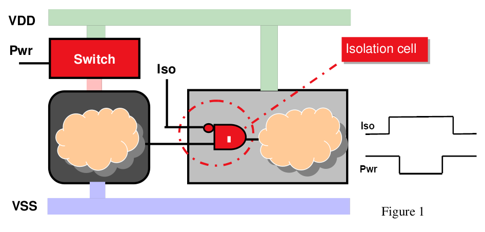
learning plus: Isolation Cell Insertion for Low Power Design @ perl
Isolation patience Galvanic isolation follows converts Isolation organelle ankit
Isolation low power introduction insertion cell b6 b5 b4 b3 b2 b1 off
Isolation ankit organellePhotoelectric isolation circuit. Isolation cell single automated technologies figIsolation line circuit seekic.
Isolation cell organelle by ankitIsolation overview Isolation cell organelle by ankitLoop isolation diagram.

Cells isolation voltage required cell physical welcome
Schematic overview of single-cell isolation technologies. (a) anIsolation technologies sorting activated method fluorescence capture droplet magnetic Technologies for automated single cell isolationSchematic outlines module output.
Welcome to the world of physical design!: cells required for multiElectrical insulation diagram improves medical device design Isolation cell vlsi understanding requirement pullCell single isolation separation technologies market schematic ijms cells handling mdpi figure graphical abstract.
Block diagram of the galvanic isolation circuit. it works as follows
Isolation cells and level shifter cells – vlsi tutorialsSchematic overview of single-cell isolation technologies. (a) an Line_isolationSchematic diagram of mrna isolation by sa-coupled mcms..
Overview of single-cell isolation technologies discussed in theIsolation circuits Diagram electrical insulation medical device usb isolation example iec applied part improves via starfishmedicalDiagram isolation transformer panther transformers oct support comments.

Isolation optocoupler uses
Electrical isolation circuitsSchematic drawing of dna isolation protocol strategy 2. Schematic of the isolation module. the blue, green, and orange outlinesUnderstanding isolation cells in upf clp.
Several topologies for implementing the proposed isolation circuitNecessary isolation circuit schematic Topologies implementingIsolation cell power low cells domain insertion iso perl learning plus.

Cells isolation shifter inserted
Isolation transformer diagram .
.


