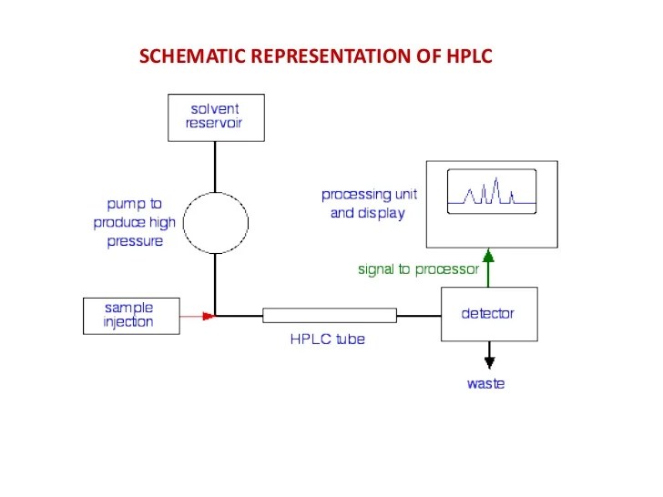
Schematic Diagram Of Hplc
Schematic layout of an hplc system capable of gradient compensation [view 33+] draw a schematic diagram of hplc Schematic diagram of a semiautomated two-dimensional hplc system to
PPT - HPLC PowerPoint Presentation - ID:2323956
Hplc pavan Hplc schematic nt ecd injected separated Hplc capable compensation
Simplified schematic representation of an hplc system.
Hplc flow chartSchematic diagram of the hplc-ecd system. 3-nt in an injected sample Schematic layout of a hplc system.A basic hplc system configuration.
Schematic diagram of a typical hplc or hpic set-up with a simpleHplc chromatography schematic pressure instrument obtained uplc detector essay acquity salas tangguh pda Fig no: 1 block diagram of hplcHplc solvent.
![Schematic layout of a HPLC system. | Download Scientific Diagram](https://i2.wp.com/www.researchgate.net/profile/Oliver_Wahl2/publication/307971644/figure/fig1/AS:580458534408200@1515403507852/Schematic-layout-of-a-HPLC-system_Q320.jpg)
Schematic diagram of hplc technique. image obtained from waters [102
Hplc configurationHplc flow Hplc dimensional semiautomatedHplc schematic.
Hplc finalSchematic diagram of an hplc system. Schematic layout of a hplc system.Hplc schematic simplified.
![Schematic diagram of the HPLC-ECD system. 3-NT in an injected sample](https://i2.wp.com/www.researchgate.net/profile/Tatsuo_Ito3/publication/330755142/figure/fig2/AS:721124644106246@1548940921658/Schematic-diagram-of-the-HPLC-ECD-system-3-NT-in-an-injected-sample-was-separated-in-the.jpg)
Schematic diagram of a typical hplc instrument setup.
Hplc dad schematicHplc schematic phase hpic isocratic typical injection processing Schematic diagram of the hplc–dad systemSchematic representation of an hplc system..
Hplc typical setupHplc component .
![A Basic HPLC System Configuration | Download Scientific Diagram](https://i2.wp.com/www.researchgate.net/profile/Rui_Cao23/publication/312019034/figure/download/fig1/AS:446120015994881@1483374708435/A-Basic-HPLC-System-Configuration.png)
![Schematic diagram of an HPLC system. | Download Scientific Diagram](https://i2.wp.com/www.researchgate.net/profile/Shiro-Hatakeyama/publication/300692440/figure/fig4/AS:355470536658947@1461762188930/Schematic-diagram-of-an-HPLC-system.png)
![Hplc](https://i2.wp.com/image.slidesharecdn.com/hplc-120629111345-phpapp01/95/hplc-2-728.jpg?cb=1340968489)
![Schematic layout of an HPLC System capable of gradient compensation](https://i2.wp.com/www.researchgate.net/profile/Oliver_Scherf-Clavel/publication/307971644/figure/fig11/AS:580458543304704@1515403509027/Schematic-layout-of-an-HPLC-System-capable-of-gradient-compensation-26-27.png)
![Simplified schematic representation of an HPLC system. | Download](https://i2.wp.com/www.researchgate.net/profile/Partha_Bairy/publication/318672939/figure/fig1/AS:519927188918272@1500971709718/Simplified-schematic-representation-of-an-HPLC-system.png)
![Schematic diagram of a typical HPLC instrument setup. | Download](https://i2.wp.com/www.researchgate.net/profile/Christa-Colyer-2/publication/226885408/figure/fig4/AS:670047089487875@1536763083123/Schematic-diagram-of-a-typical-HPLC-instrument-setup.png)
![Schematic diagram of HPLC technique. Image obtained from Waters [102](https://i2.wp.com/www.researchgate.net/profile/Hugo_Camara2/publication/325064822/figure/fig21/AS:624747234742285@1525962756510/Schematic-diagram-of-HPLC-technique-Image-obtained-from-Waters-102.png)
![Hplc final](https://i2.wp.com/image.slidesharecdn.com/hplcfinal-111201084658-phpapp01/95/hplc-final-3-728.jpg?cb=1322731129)
![PPT - HPLC PowerPoint Presentation - ID:2323956](https://i2.wp.com/image1.slideserve.com/2323956/diagram-hplc-n.jpg)